This bulletin is for the purpose of helping customers solve operation/connection issues on Custom Dynamics® LED replacement turn signal clusters with plug-in bases. Please review this bulletin if you are no longer seeing proper illumination for one or all functions of the LED or you are in the process of installing the LEDs and find you are not getting the correct response from the LED. An example of this is installing a PB-R-1156 and find there is no illumination with the LED when inserted into the 1156 socket. If you have questions please call Custom Dynamics® at 1(800) 382-1388.
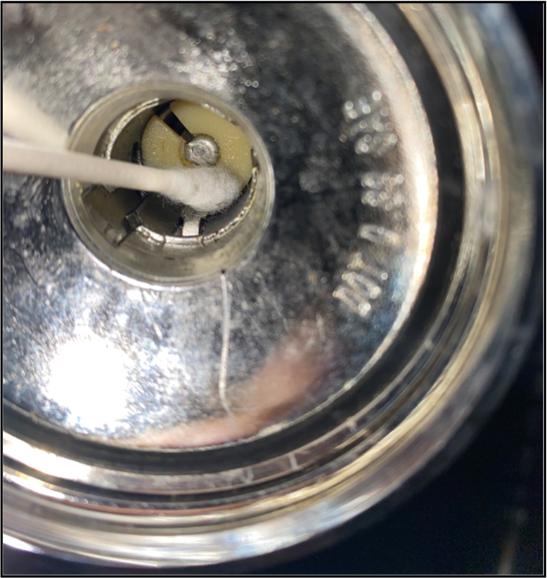
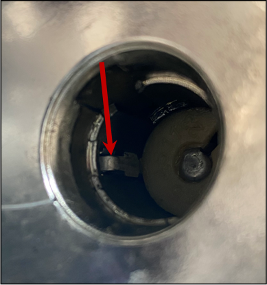
Confirming socket condition
1. Ensure socket is free from Di-electric grease or corrosion.
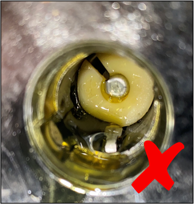
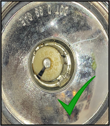
2. Using a NON CONDUCTIVE item, make sure the socket spring is moving up and down freely. Check that the ground connection tab is properly raised from the socket and in place.
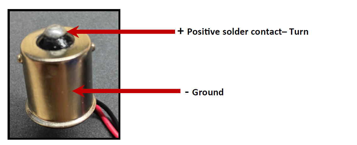
Bulb Base Connection Configuration
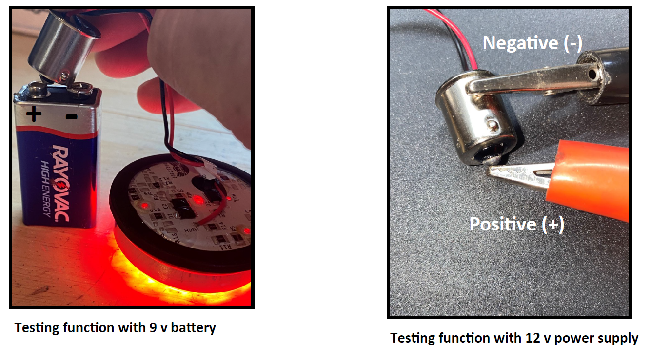
Bench Testing the operation of the LED Cluster
Using a 9 volt battery or 12 volt power supply ( ie. Motorcycle / Car battery with jumper wires)
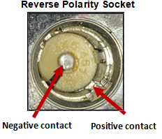
Touch the negative (-) to the base and positive (+) to the solder contact
Reverse Polarity
Polarity describes the direction in which electricity will flow. Current flows from the positive pole to the negative pole. Reverse Polarity then is a term that describes an electrical condition in which the positive [ + ] power wire is connected to the terminal on the receptacle intended for the ground [ - ] wire and the ground [ - ] wire is connected to the terminal on the receptacle intended for the positive [ + ] power wire. The wires are, in effect, "reversed." This condition unintentionally occurs at the factory when the single intensity 1156 turn signals are installed.
So why does this not matter when we use incandescent bulbs? Well, incandescent bulbs are different from LED clusters in the respect that electricity can flow either way through the them, positive to negative or vice versa. An LED cluster will only let electricity flow one way through, Positive to negative.
When we have confirmed that there is power all the way to the turn signal socket, as well as confirmed that the LED cluster lights up, then reverse polarity is usually the issue. To remedy this condition, we need to confirm it by using a test light probe, then re-wire the cluster. Follow the instructions below.
- Attach the connection clamp from the test light to a ground stud or negative battery terminal on the bike.
- Turn the ignition on.
- Touch the test probe to the [ + ] center contact, the test light would normally light up here, but if we have reverse polarity, we will not have any current , so the test light will not come on.
- Now touch the test probe to the [ - ] ground wall contact. If reverse polarity is present, the test light should come on. To correct this issue, we will modify the cluster.
- Turn Ignition off.
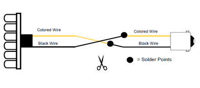
- Cut both wires on the 1156 cluster halfway between the connector base and the cluster.
- Next, you will need 2 pieces of heat shrink tubing to cover the connections, a soldering iron and a heat gun.
- Strip back the insulation on both ends of wires, then twist together as follows: - The connector base end black wire will attach to the colored wire on the cluster - The connector base end colored wire will attach to the Black wire on the cluster
- Apply solder to the connections.
- Cover solder connections with heat shrink tubing and use the heat gun to shrink the tubing.
- Re-install the cluster and test for function on the bike.